Pages

Sunday 5 May 2013

(HAL-5 endoskeleton system)


The fifteen kilogram battery-powered suit detects muscle movements through electrical signal flows on the skin surface. These currents are picked up by the sensors and sent to the computer, which translates the nerve signals into signals of its own for controlling electric motors at the hips and knees of the exoskeleton, effectively amplifying muscle strength. HAL stands for "hybrid assistive limb"; HAL-5 is the latest version of the suit.


HAL-5 (Hybrid Assistive Leg), the robotic exoskeleton developed to help humans lift and carry a greater load, will now help cary a Japanese quadtiplegic to the top of a moutain.

"We developed the exo-skeleton type power assist system to realize the walking aid for the gait disorder person. At the present time, HAL is state of the art power assist system in the world. Some sensors such as angle sensors, myoelectrical sensors, floor sensors etc. are adopted in order to obtain the condition of the HAL and the operator. All of the motordrivers, measurement system, computer, wireless LAN, and power supply are built in the backpack. Using the battery attached on the waist, HAL works as the complete wearable system."
Prof. Sankai, Univ. of Tsukuba / CYBERDYNE Inc

(HAL-5 endoskeleton system)
Seiji Uchida, paralyzed from the neck down as a result of a 1983 traffic accident, will take a cable car to a point close to the summit of Breithorn, a 1,164-metre Swiss peak. Alpine mountaineer Ken Noguchi will carry him to the top, with the assistance of the HAL-5 exoskeleton.
HAL provides enough additional strength to lift an additional eighty kilograms of weight. The trek is planned for this summer.
Robotic exoskeletons have played a part in science fiction stories for decades. In his 1968 novel A Specter is Haunting Texas, science fiction writer Fritz Leiber describes specialized exoskeletons used to help human beings who grew up under microgravity conditions survive on the Earth's surface:

This truly magnificient, romantically handsome, rather lean man was standing on two corrugated-soled titanium footplates. From the outer edge of each rose a narrow titanium T-beam that followed the line of his leg, with a joint (locked now) at the knee, up to another joint with a titanium pelvic girdle and shallow belly support. From the back of this girdle a T-spine rose to support a shoulder yoke and rib cage, all of the same metal. The rib cage was artistically slotted to save weight, so that curving strips followed the line of each of his very prominent ribs....The motors were controlled by myoelectric impulses from his ghost muscles transmitted by sensitive pickups buried in the foam-padded bands.
(Read more about the titanium exoskeleton)

technology behind iron man


Iron Man, the most technologically advanced super-hero to ever hit film, is making a triumphant return to the big screen this week. Now sneak a peek into the inventions that power Tony Stark in his quest to save the world.
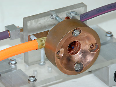
The arc reactor
The power that drives Iron Man's fantastic exploits comes from the fictional "arc reactor." The movie reveals the one embedded in Stark's chest is slowly poisoning him with palladium, which in real life actually can be toxic, although probably not in the fanciful way depicted in the movie. 
It might seem odd at first that a reactor might rely on a precious metal akin to platinum, but this mystery clears somewhat given palladium's central role in claims regarding "cold fusion." Experiments two decades ago suggested nuclear fusion at close to room temperature, raising hopes of a cheap and abundant source of energy. Although most scientists now regard cold fusion as bunk, researchers at the U.S. Navy's Space and Naval Warfare Systems Center are still pursuing it, suggesting that Iron Man's use of cold fusion in warfare might not be so farfetched after all.
New elements
To avoid death from palladium, Stark instead creates an entirely new element to use in the arc reactor. The novelizations that the movie is based upon notes this new element is "vibranium," a fictional energy-absorbing substance that pops up regularly in the Marvel Universe, notably in Captain America's shield.
Scientists are in fact endeavoring to create new elements, with the most recent announcement coming in April of element 117, which bears the temporary name ununseptium. Unlike the vibranium Stark manufactures, the new elements scientists have actually created so far are all unstable, with only six atoms of ununseptium detected before they decayed into lighter elements. Still, physicists do conjecture the existence of an "island of stability" of super-heavy elements that don't break down immediately, which the vibranium in the film might belong to.
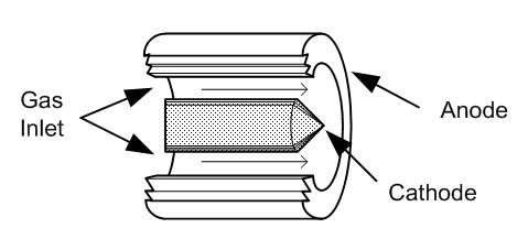
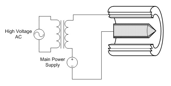
The fictional vibranium and the real ununseptium were both created using cyclotrons, or circular particle accelerators that can smash atoms together to generate heavier elements. Real scientists would probably not build cyclotrons in their basements as Stark did, however, and would probably want a lot more shielding to avoid death from radiation.
Hot weapons, flying saucers
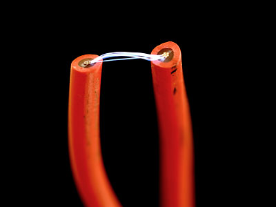
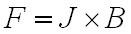
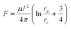
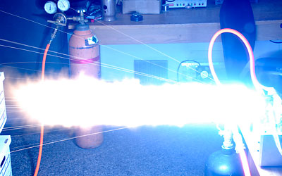
Iron Man and the main villain of the film, Ivan Varko, fight each other using weapons apparently based on plasma, the electrically charged state of matter that makes up stars and lightning.
Iron Man fires pulses of the stuff, while Varko, who resembles the Marvel super-villain "Whiplash," uses what the novelizations say are plasma whips made of tungsten carbide wrapped in copper wire, with the tungsten carbide supposedly remaining magnetic even at extraordinarily high temperatures, thus holding the copper in place when it gets transformed into plasma at nearly 4,900 degrees F (2,700 degrees C).
Scientists actually are developing weapons based on plasma, such as the StunStrike, which essentially fires a bolt of lightning, creating an electrical charge through a stream of plasma. Researchers have recently even created what appears to be ball lightning in microwave ovens, which Iron Man's "repulsor blasts" resemble.
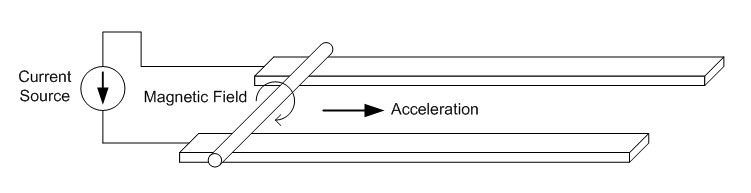
Iron Man also flies around with plasma thrusters. Although it seems unlikely that disk-shaped engines small enough to fit into boots or gloves could fly a man around at supersonic speeds, there are inventors who are say they are developing aircraft — flying saucers, no less — that fly around using plasma, electrically generating plasma on their surfaces and electromagnetically manipulating it for propulsion.
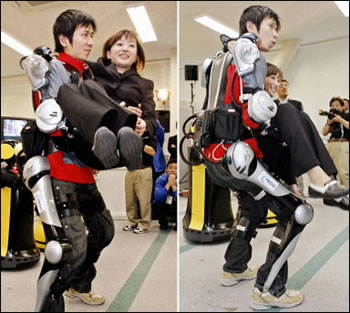
Suits of armor
Stark's most outstanding invention of the movie is, of course, the Iron Man suit that brings all these technologies together. Scientists are actually creating exoskeletons that can amplify strength, with two companies developing prototypes for the U.S. Army and researchers also manufacturing exoskeletons in Japan.
The armors shown in the movie show the mind-boggling ability to protect their wearers from blows that might otherwise liquefy them. One might imagine there are incredibly strong cushions inside the suits, and in fact researchers have made foams made of carbon nanotubes, or pipes just nanometers or billionths of a meter wide, that are exceptionally springy and strong, perhaps just what Iron Man needs to prevent every bone in his body from being broken during fights.
Mindless drones
The villain of the movie might have the right idea, though, when it comes to how future warfare will actually be waged. Instead of relying on flying soldiers, Varko employed robots. These could keep soldiers from dying on the field and perform at levels and in conditions that people never could. The growing use of drones in the military clearly shows how useful commanders find them, and real soldiers even seem to love their robot brethren.
Unfortunately, as the movie also points out, robots can get hacked, with reports emerging in December of Iraqi militants intercepting live video feeds from U.S. Predator drones, potentially gaining information they needed to evade or spy on U.S. military operations. Perhaps keeping an Iron Man or two around might not be too much of a fantasy after all.

Magnetoplasmadynamic (MPD) Thruster Design


Yes, I know - the name is scary, but the principles on which it works are relatively simple and are found in items that you use everyday. That may sound like plain old ridiculousness, but let's take a quick look at perhaps one of the simplest forms of the electric motor. It is constructed using a current source (battery, etc.), two conductive rails, and a round conductor as shown in figure 1.

Fig.1: Lorentz Force Motor

In this example, a current flows into the nearer rail, through the round conductor, and then back through the far rail to the current source. The current through the conductors cause a magnetic field as shown, and the interaction between the flowing electric charges in the rod and the magnetic field produce a force on the rod that cause it to accelerate away from the current source. This is known as the Lorentz Force, and it can be applied to any conductive material.* For the purposes of the MPD thruster a typical propellant is hydrogen gas, which does not normally conduct electricity. If hydrogen was going to be the "round conductor" in this new type of thruster, how do we get it to conduct electricity? This is easy enough, since just about everyone has seen a gas conduct electricity.


Fig. 2: Ionized Gas (Plasma) in a Spark

Sparks are actually just very hot gasses that have had electrons stripped from the individual atoms. Since the gas now contains free electrical charges it can conduct electricity and can act as the conductor between the two rails of the accelerator. Matter that has been heated to the point that it becomes electrically conductive is called a plasma. Now, all we have to do is make a few small adjustments to the Lorentz Force accelerator in figure 1 and we'll have all of the basic elements of a complete MPD thruster.

Fig. 3: Lorentz Accelerator Using Plasma Conductor

All we've done here is added a source of propellant gas and replaced the conducting rod with a plasma. Since the plasma now carries the current, it will feel the same accelerating force as did the original rod. This results in the plasma being accelerated out of the end of the channel formed by the two electrodes, providing thrust. We now have all of the basic elements needed to understand how a MPD thruster works, though there are plenty of improvements that can and will still be made to this design.

The complete design is divided into several functional components, which will be examined in more detail later. Here is a quasi-block diagram that illustrates how all of the components combine to create a complete thruster package.


Fig. 4: System Block Diagram

The capacitor bank stores electrical energy supplied from a charging circuit, and is connected to the two electrodes in the nozzle (inner and outer electrodes) through an ignition circuit. The ignition circuit serves to begin the discharge between the two electrodes, and provides an electrically conductive path for current supplied from the capacitor bank to flow through. The gas injection system injects the propellant gas (argon in this case) into the nozzle chamber, which is subsequently ionized and accelerated out of the nozzle by the current from the capacitor bank. The high speed propellant gas leaving the nozzle creates thrust. A more detailed look at these systems is presented below.

Electrodes / Nozzle (More in Depth Nozzle Information)

In the simple example above a pair of ordinary conductive strips was used. However, because of the extreme conditions that exist inside of a plasma thruster, significantly more thought is required to avoid the complete destruction of the electrodes. A popular geometry for the electrodes is a hollow cylinder with a smaller cylinder centered axially, as shown in figure 5.

Fig. 5: Nozzle Geometry Cut-Away View

This is a convenient geometry for several reasons, including the fact that the anode can have much more mass than the cathode. This helps with cooling, since in an arc discharge much of the thermal energy gets deposited at the anode. Care still must be taken to prevent the cathode from melting. In this case I used a 1/4" diameter tungsten rod as the cathode due to it's ability to tolerate very high temperatures. The completed nozzle assembly is shown below.


Fig. 5: Completed Nozzle Assembly

Here you can see the large outer copper electrode with the smaller tungsten electrode protruding from the opening. The orange tubing on the left is the propellant gas feed line, which supplies Argon to the thruster at approximately 150 PSI. The two purple cables are from the power supply. There is a terminal block attached directly to the anode, which can be seen in the upper right. The cathode extends through the Lexan insulator and is press-fit into a copper block which has attached a second terminal block. It can be seen on the left of the photo.

Capacitor Bank (More in Depth Capacitor Bank Information)

One of the attractive properties of MPD thrusters is that they are capable of very high power levels, and can easily consume millions of watts of power. This is encouraging when looking toward future space missions, however it presents a formidable problem for (at the very least) testing such systems on the ground due to the enormous power supplies that these power levels would entail. A popular method of getting around this problem, at least for testing purposed, is to use a capacitor bank to store large quantities of energy and then run the thruster for only a few fractions of a second at full power. Often this is enough time for the internal conditions of the thruster to stabilize so useful measurements of their long term performance can be made.

One of my intentions for this project was to be able to operate my thruster in the megawatt range. This involves storing a large amount of energy which in turn requires a large capacitor bank. I was able to obtain 128 electrolytic capacitors from eBay rated at 3.6mF at 350V. This comes to just over 28kJ of energy stored. For estimation purposes, if we suppose that the discharge might last anywhere from 1ms to 10ms, then the average power consumption of this thruster would be between 2.8MW and 28MW with the possibility of much higher peak power. I assembled these capacitors into two stacks of 64 capacitors each, and connected the two stacks in series to obtain an overall equivalent of 115mF at 700V. The stacks are shown below.


Fig. 5: Assembled Capacitor Bank

One of the most important features of this capacitor bank is the use of heavy duty aluminum bars bolted tightly together for conductors. At first glance they seem as though they are structural elements, not electrical. The reason for this is that at the current levels encountered in this design, the conductors experience tremendous forces that can tear apart less rugged designs. One of the unexpected difficulties of working with this sort of equipment is that they rarely fail the way small electronics do. When breadboarding a small circuit, a mistake in component current ratings might result in an IC burning out or a resistor smoking. In this thruster design, underestimating the current and forces involved are more likely to result in portions of the device tearing apart or launching themselves into the air. At one point, I had a copper cable about 3/4" in diameter rip right in half. Try doing that by hand if you want to get an idea of the kind of forces involved.

Discharge Initiation / Ignition Circuit (More in Depth Ignition Circuit Information)

As mentioned earlier, this type of thruster requires high temperature, electrically conductive plasma in order to be able to carry the current necessary to produce the force that accelerates the propellant, but simply injecting propellant between the two electrodes doesn't necessarily mean these conditions will exist. In fact, the gas will only ionize and become a plasma on its own if the voltage across the electrodes exceeds the breakdown potential for the gap length and gas used. For a moderate gap, this can easily be tens of thousands of volts. Due to the limits of the power supply and capacitor bank used, this is not feasible. Instead, a separate ignition circuit was designed to produce a very high voltage between the two electrodes for a short period of time. This high voltage will be sufficient to start the arc discharge. The circuit uses a high frequency high voltage AC source and a coupling transformer to do this.

Fig. 5: Transformer Coupled Ignition Circuit 

Initially, the resistance through the argon propellant between the electrodes prevents any current from flowing between the electrodes. The ignition circuit applies a large voltage of several tens of thousands of volts between the electrodes, which causes a spark to jump between the two electrodes. This spark is composed of electrically conductive ionized gas, providing a low resistance path through which current supplied by the capacitor bank can flow. A portion of the energy supplied by the capacitor bank goes towards ionizing any propellant gas in the nozzle, thus maintaining a path for the discharge current.

Propellant Gas Injection System

The propellant gas used in this design is Argon, which was chosen for it's availability and it's monatomic structure. This means that Argon gas exists as single Argon atoms, whereas Oxygen, Nitrogen, and Hydrogen exist as molecules of paired atoms. The energy spent separating these molecules prior to ionizing them does not contribute to accelerating the gas, and as a result this energy is wasted. Since Argon exists as a single atom, it does not have this disadvantage.

Argon is available from most welding supply stores in compressed cylinders. Unfortunately, the pressures in these cylinders are too high to easily control, so a regulator is used to reduce the pressure to a manageable level. In order to maintain flow rates as high as possible, a surge tank is employed. A gas solenoid valve is employed to control the flow of the propellant gas. This system is capable of delivering Argon at a rate of 5.45 SCFS (standard cubic feet per second.) This is equivalent to approximately 0.6 grams per second.


Fig. 6: Gas Injection System

Theory of Operation

The aim of this thruster topology and design, as with any thruster, is to maximize the efficiency of the thruster, especially with respect to the use of the propellant gas. This design has a particular advantage in that area, as the forces developed on the propellant gas arise from electromagnetic forces, rather than from thermal expansion. Thermal expansion thrusters are limited by the maximum temperature that the nozzle can withstand. Electromagnetic thrusters are not directly limited in this manner, and are therefore capable of much higher exhaust velocities (and therefore higher thrust per mass of propellant) making them especially fuel efficient.

The principle method of accelerating the propellant is, as discussed earlier, by the application of the Lorentz force to electrically conductive propellant. The magnitude of the force exerted on the gas is then given as


Eq. 1: Lorentz Force Equation

where F is the force in Newtons, J is the total current, and B is the magnetic flux density. The magnetic flux density B is also a function of the total current flowing, so the force exerted on the propellant is actually related by the total current squared. This provides a strong incentive to operate the thruster with the largest tolerable currents. A more correct approximation can be obtained by integrating the force density over the volume of the thruster nozzle. This yields the total force as [1]

Eq. 2: Total Force as Computed by Integration of Force Density

where F is the force in Newtons, J is the total current, u is the magnetic permeability of free space, ra is the radius of the anode, and rc is the radius of the cathode. Based on an arc current of 27kA and the dimensions of my nozzle, equation 2 predicts a peak force of 140 N, with the following discharge profile

Fig. 7: Predicted Discharge Current
Results

The most impressive result obtained from this experiment is the discharge itself, shown below.


Fig. 8: Thruster Exhaust

The actual performance of the thruster is somewhat less impressive than predicted, with peak thrust in the range of 20-40 N and peak currents of 30-40kA. These levels of performance more closely approximate those that would be expected from an electro-thermal thruster. This discrepancy was expected, and is caused by the fact that my thruster was operated at atmospheric pressure, whereas  these thrusters are typically operated in near vacuum conditions. The higher operating pressure increased the density of the gas and therefore the rate at which the ions collided with each other, resulting in the loss of momentum. The fact that the thruster's performance was near that predicted for a thermo-electric accelerated was also expected, as the dominant thrust mechanism was the thermal expansion of the propellant gas. Predictably, this corresponded to extensive wear and loss of electrode material due to the extreme temperatures and loss of self-shielding mechanisms provided by low pressure operation.  

* If you've seen "The Hunt for Red October" you may remember the silent "caterpillar" drive that was on the Red October. This is called a magnetohyrdodynamic drive, and it's almost exactly the same as the Lorentz motor in figure 1, except that MHD drives use water as the conducting material and may use permanent magnets instead of relying on the magnetic field causes by the electrical current.

References

[1] R. G. Jahn, Physics of Electric PropulsionMineola: Dover Publications, Inc., 2006, pp. 244